Syllabus
1 Operational Amplifier Fundamentals, 07 Hours CO1
1.1 Basic Op Amp Configurations and Ideal Op Amp Parameters, Circuits Analysis of Op-Amp, Simplified Op Amp Circuits Diagram, Frequency response for Open Loop and Closed Loop Configurations.
1.2 Understanding the op-amp datasheet for design purposes. Numerical based on op-amp parameters.
2 Linear Applications of OP-AMP 07 Hours CO2
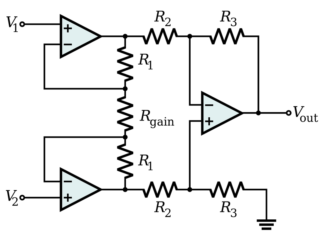
2.1 Shunt-Shunt feedback (Inverting Amplifier), Series shunt feedback (Non-Inverting Amplifier) Summing Amplifier, Averaging Amplifier, Difference Amplifier, Instrumentation Amplifier Applications. Instrumentation Amplifier (IC AD620).
2.2 Integrator/Differentiator using OP-AMP Current-to-Voltage Converters, Voltage-to-Currents Converters, Grounded load V/I Converter V-F and F-V Converters. Sample-and-Hold circuit.
3 Active Filters, 06 Hours CO2
3.1 The Transfer function, First-Order Active Filters.
3.2 Standard Second- Order Responses, KRC Filters, Multiple-Feedback Filters.
4 Non-linear Applications of OP-AMP 07 Hours CO3
4.1 Voltage Comparators, Comparator Application, Schmitt Triggers, Precision Rectifier, Peak Detectors.
4.2 Mono-shot Multi-vibrator, Astable Multi-vibrator, Triangular/saw-tooth waveform Generator.
5 Regulators and Data Converters 08 Hours CO4
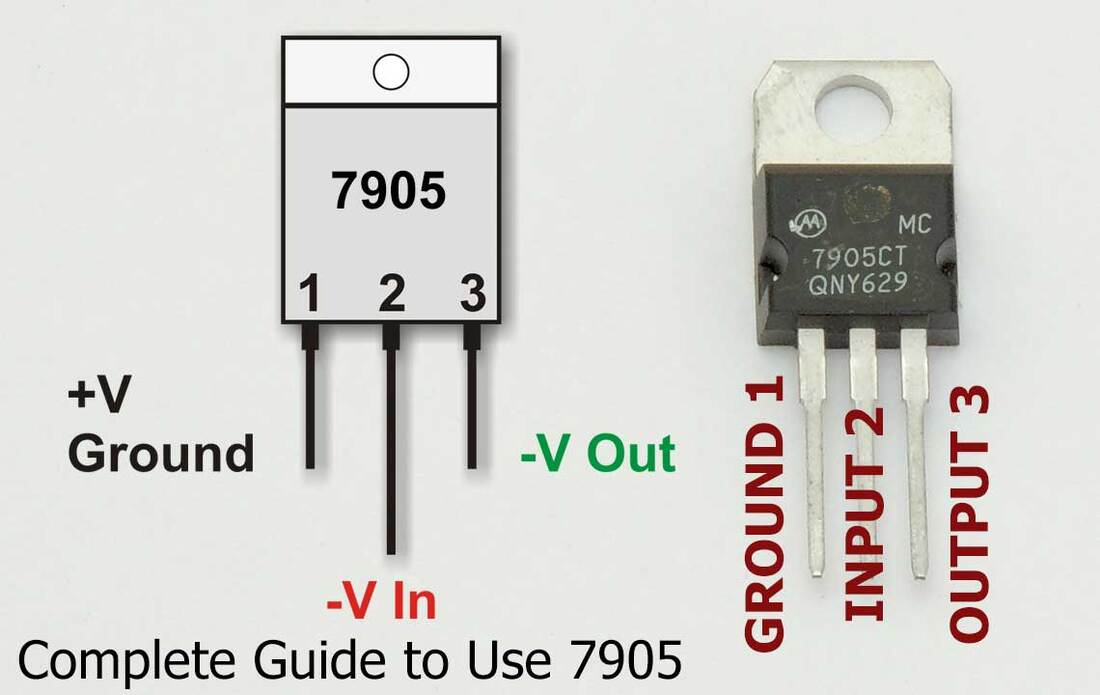
5.1 Functional block diagram of Voltage Regulators, Fixed voltage Regulators (78XX and 79XX) . Variable Voltage Regulators (LM317 and CA723)
5.2 General techniques for ADC and DAC and their applications. For example 0808, 0809.
6 Waveform Generators and special IC’s 10 Hours CO4
6.1 Oscillators using OP-AMP (RC-phase shift and Wien Bridge oscillators), Quadrature Oscillators.
6.2 Monolithic Timer (NE555).
6.3 Phase-Locked Loops,
1.1 Basic Op Amp Configurations and Ideal Op Amp Parameters, Circuits Analysis of Op-Amp, Simplified Op Amp Circuits Diagram, Frequency response for Open Loop and Closed Loop Configurations.
1.2 Understanding the op-amp datasheet for design purposes. Numerical based on op-amp parameters.
2 Linear Applications of OP-AMP 07 Hours CO2
2.1 Shunt-Shunt feedback (Inverting Amplifier), Series shunt feedback (Non-Inverting Amplifier) Summing Amplifier, Averaging Amplifier, Difference Amplifier, Instrumentation Amplifier Applications. Instrumentation Amplifier (IC AD620).
2.2 Integrator/Differentiator using OP-AMP Current-to-Voltage Converters, Voltage-to-Currents Converters, Grounded load V/I Converter V-F and F-V Converters. Sample-and-Hold circuit.
3 Active Filters, 06 Hours CO2
3.1 The Transfer function, First-Order Active Filters.
3.2 Standard Second- Order Responses, KRC Filters, Multiple-Feedback Filters.
4 Non-linear Applications of OP-AMP 07 Hours CO3
4.1 Voltage Comparators, Comparator Application, Schmitt Triggers, Precision Rectifier, Peak Detectors.
4.2 Mono-shot Multi-vibrator, Astable Multi-vibrator, Triangular/saw-tooth waveform Generator.
5 Regulators and Data Converters 08 Hours CO4
5.1 Functional block diagram of Voltage Regulators, Fixed voltage Regulators (78XX and 79XX) . Variable Voltage Regulators (LM317 and CA723)
5.2 General techniques for ADC and DAC and their applications. For example 0808, 0809.
6 Waveform Generators and special IC’s 10 Hours CO4
6.1 Oscillators using OP-AMP (RC-phase shift and Wien Bridge oscillators), Quadrature Oscillators.
6.2 Monolithic Timer (NE555).
6.3 Phase-Locked Loops,
Lecture 1
Operational Amplifier Fundamentals
What is an Operational Amplifier?
- An op-amp is a high-gain electronic voltage amplifier with differential inputs and a single-ended output.
- It's a versatile building block in analog circuits, used to perform various functions like amplification, filtering, signal conditioning, and mathematical operations.
Key Characteristics:
- High Open-Loop Gain: Op-amps have extremely high gain without feedback, typically in the range of 100,000 to over 1 million. This immense gain is harnessed through feedback to achieve precise control over the output.
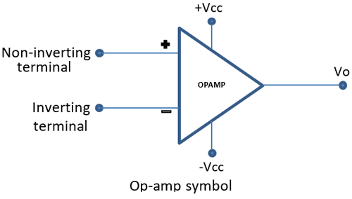
- Differential Inputs: The op-amp amplifies the difference between the voltages applied to its two input terminals.
- Single-Ended Output: The output produces a voltage relative to a common ground.
- High Input Impedance: The input terminals draw very little current, minimizing loading effects on the signal source.
- Low Output Impedance: The output can deliver a substantial amount of current to drive external loads.
Feedback and Closed-Loop Configuration:
- Feedback is a crucial concept in op-amp circuits. It involves connecting a portion of the output back to the input.
- This feedback controls the gain and establishes a stable, predictable output behavior.
- Circuits employing feedback are called closed-loop configurations.
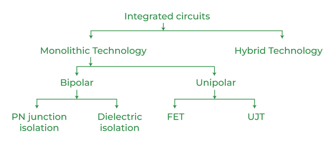
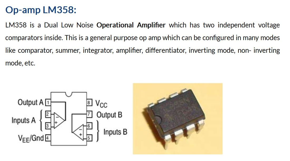
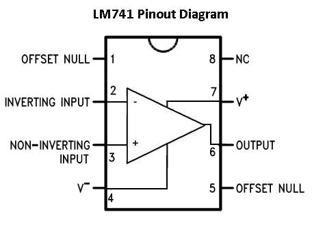
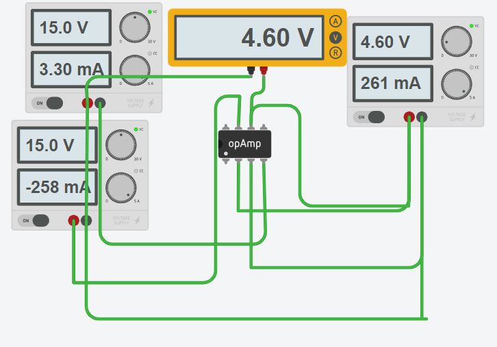
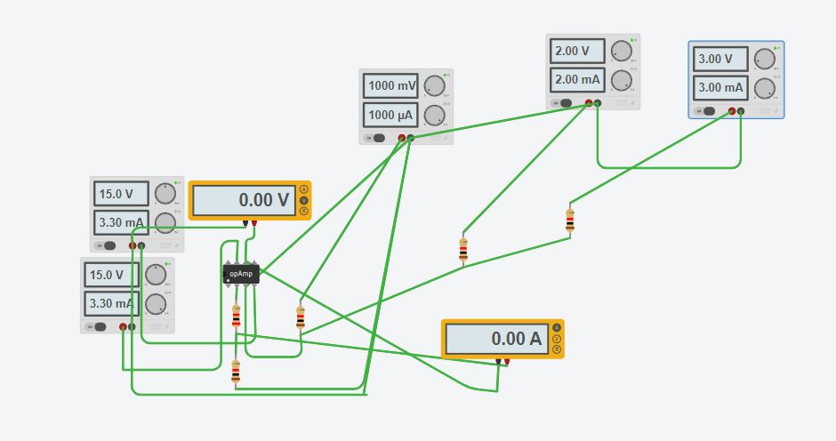
OPAMP ICs
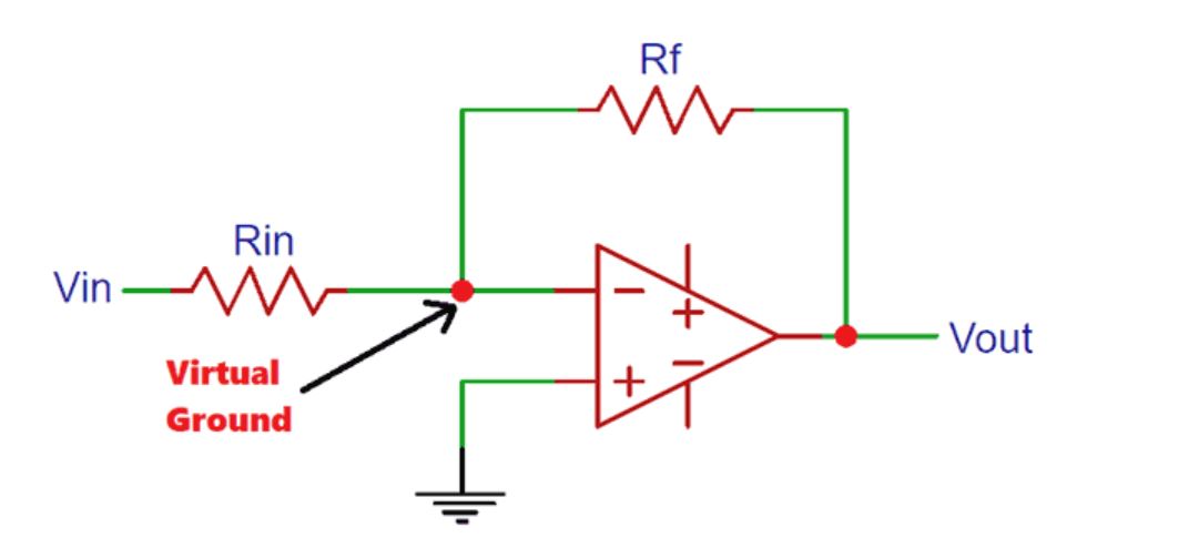
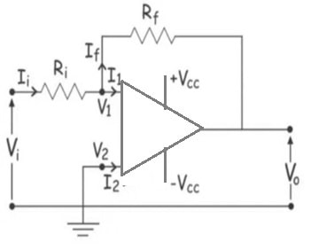
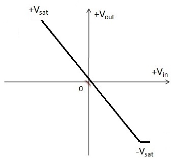
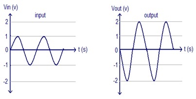
Inverting Amplifier
|
|
|
|
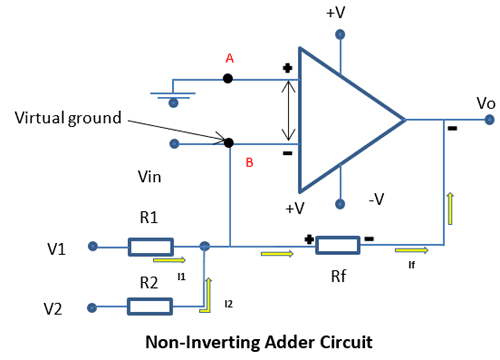
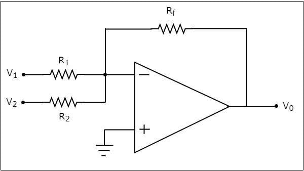
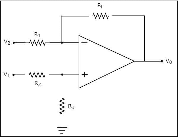
Adder
Lab 1

Classroom:
A3-Batch
https://classroom.google.com/c/NjUwNjg1NDQ2MTM1?cjc=cmfnk4k

Mini Project report format
| aica__mini_project.zip |
IA 2
IA1 questions
1. Discuss the concept of an ideal operational amplifier (op-amp). Explain the parameters that characterize an ideal op-amp.
2. Compare and contrast the open-loop and closed-loop configurations of operational amplifiers. How does the frequency response vary between these configurations? Provide diagrams to support your explanation.
3. Explain the working principle of the inverting amplifier and derive the expression for its voltage gain. Also, discuss the significance of feedback in this configuration.
4. Describe the operation of the instrumentation amplifier using the IC AD620. Discuss its advantages and applications in instrumentation systems.
5. Define the transfer function of an active filter. Explain the concept of first-order active filters and derive the expression for their transfer function.
6. Discuss the characteristics and applications of second-order active filters. Compare and contrast KRC filters with multiple-feedback filters.
7. Explain the working principle of a Schmitt trigger. How does it differ from a conventional comparator? Discuss its applications in signal conditioning circuits.
8. Discuss the operation of astable multivibrators and their applications. Provide the circuit diagram and explain the waveform generation process.
Oral questions:
Operational Amplifier Fundamentals (CO1)1.1 Basic Op Amp Configurations and Ideal Op Amp Parameters
- Explain the difference between inverting and non-inverting amplifier configurations.
- What are the ideal parameters of an operational amplifier (e.g., open-loop gain, input impedance, output impedance)?
- How can you analyze the gain of a simple op-amp circuit using voltage divider rules?
- Describe the frequency response of an op-amp in open-loop and closed-loop configurations. How do they differ?
- How do you find key specifications like gain-bandwidth product and input offset voltage in an op-amp datasheet?
- Given an op-amp datasheet and a desired gain for your circuit, can you calculate the appropriate resistor values?
- A datasheet specifies a typical open-loop gain of 100 dB. What does this tell you about the op-amp's behavior in a circuit?
- Explain the operation of an inverting amplifier circuit and derive its gain formula.
- How does a non-inverting amplifier differ from an inverting amplifier, and what is its gain formula?
- Design a summing amplifier circuit to add three input voltages with specific weights.
- Describe the basic principle behind an integrator circuit using an op-amp. How can you calculate its output voltage for a given input signal?
- Explain the opposite functionality of a differentiator circuit and derive its output equation.
- How can you use an op-amp to convert a current signal into a voltage signal, and vice versa?
- What is the transfer function of a circuit, and how does it relate to the filter's behavior?
- Design a first-order low-pass filter circuit using an op-amp and explain its frequency response.
- Can you differentiate between a high-pass filter and a low-pass filter based on their transfer functions?
- Explain the operation of a voltage comparator circuit and its application in zero-crossing detection.
- How can you design a Schmitt trigger circuit using an op-amp and positive feedback?
- Describe the basic principle behind a peak detector circuit and its use in signal processing.
- Differentiate between a monostable multivibrator and an astable multivibrator based on their output behavior.
- How can you use an op-amp to generate a triangular waveform?
- Explain the function of a voltage regulator circuit and its role in power supply design.
- How do fixed voltage regulators like the 78XX series work to provide a constant output voltage?
- Given the datasheet of a variable voltage regulator like the LM317, can you calculate the required components to achieve a specific output voltage?
- Explain the working principle of an RC phase-shift oscillator using an op-amp.
- How does a Wien bridge oscillator differ from an RC phase-shift oscillator, and what are its advantages?
- Describe the functionalities of a timer IC like the NE555 and its applications in astable multivibrator circuits.
- In basic terms, explain the concept of a phase-locked loop (PLL) and its use in frequency synthesis.
1.1 Basic Op-Amp Configurations and Ideal Op-Amp Parameters
Explain the difference between the inverting and non-inverting configurations of an op-amp. How does the output voltage change in each configuration relative to the input voltage?
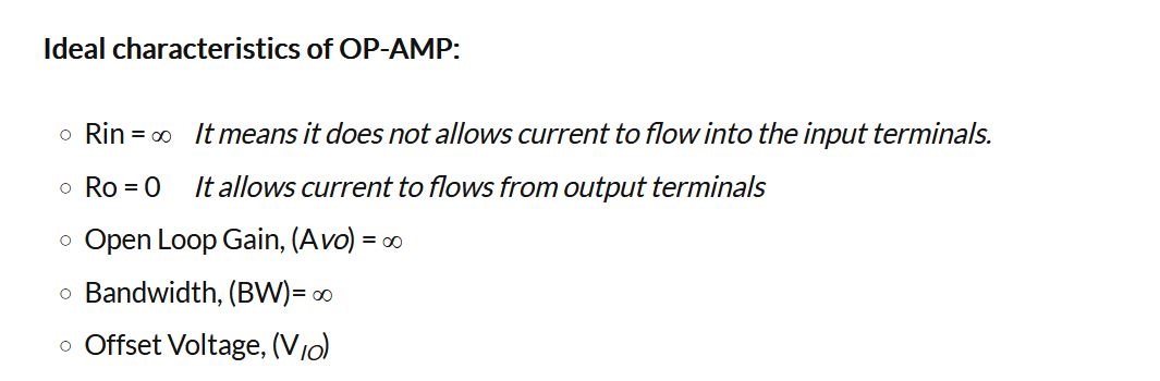
What are the ideal characteristics of an operational amplifier? Discuss concepts like infinite gain, zero input offset voltage, and infinite input impedance.
In a simplified op-amp circuit diagram, how do external resistors determine the gain of the circuit in inverting and non-inverting configurations?
How does the frequency response of an op-amp differ between open-loop and closed-loop configurations? What is the significance of this difference?
1.2 Understanding Op-Amp Datasheets and Design
When selecting an op-amp for a design project, what key parameters do you need to consider from the datasheet? Provide some examples.
A specific op-amp datasheet lists an open-loop gain of 100 dB. If you design an inverting amplifier circuit with a gain of -10, what is the expected voltage at the output for a 1 mV input signal?
How can the input offset voltage of an op-amp affect the accuracy of a circuit? Are there any design techniques to minimize its impact?
Op-amp datasheets often specify a bandwidth limitation. Explain how this bandwidth limitation can affect the performance of a circuit, particularly in high-frequency applications.
Why gain is in dB
Where OpAMP is used practically?
AD620 used in which application?
Explain the difference between the inverting and non-inverting configurations of an op-amp. How does the output voltage change in each configuration relative to the input voltage?
What are the ideal characteristics of an operational amplifier? Discuss concepts like infinite gain, zero input offset voltage, and infinite input impedance.
In a simplified op-amp circuit diagram, how do external resistors determine the gain of the circuit in inverting and non-inverting configurations?
How does the frequency response of an op-amp differ between open-loop and closed-loop configurations? What is the significance of this difference?
1.2 Understanding Op-Amp Datasheets and Design
When selecting an op-amp for a design project, what key parameters do you need to consider from the datasheet? Provide some examples.
A specific op-amp datasheet lists an open-loop gain of 100 dB. If you design an inverting amplifier circuit with a gain of -10, what is the expected voltage at the output for a 1 mV input signal?
How can the input offset voltage of an op-amp affect the accuracy of a circuit? Are there any design techniques to minimize its impact?
Op-amp datasheets often specify a bandwidth limitation. Explain how this bandwidth limitation can affect the performance of a circuit, particularly in high-frequency applications.
Why gain is in dB
Where OpAMP is used practically?
AD620 used in which application?
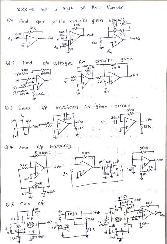
Find the gain
Find gain
What is Virtual Ground
How battery is connected in 7905
7805 minimum voltage required to start IC
Gain bandwidth product in opamp
Design circuit for gain 13.5
PWM with ic 555
Draw internal diagram of 555
if offset voltage 1mv how much voltage to apply on offset pin
Draw internal diagram of 555
if offset voltage 1mv how much voltage to apply on offset pin
Link to official Whatsapp group
Results:
| 187_elx6_x6aic_ca.xlsx_-_sheet1.pdf |
| 187_elx6_x6aicl_tw.xlsx_-_sheet1.pdf |
